Circuit Design by Steve Bringhurst "baldy3823"
Notes:T1 Calrad 45-700 audio transformer (Ocean Electronic)
T2 Bogen T724 4 watt P/A transformer (Grainger)
R1 250k ohm variable resistor
SW1 12 position single pole rotary switch (Radio Shack)
C1 .1 uf capacitor
C2 Value of C2 depends on the set up of the headsets.
(all non polar)
1) one 600 ohm impedance element = 1 uf
2) two 600 ohm imped. elements wired in parallel = 2.2uf
3) two 600 ohm impedance elements wired in series = .5 uf
4) 10k Hi "Z" headphones = .068uf to .05uf
5) two low "Z" elements in series like Stromberg
Carlsons can be run on 2.2 uf, but 4.7uf might be
a better match up.
1) 1 uF is a good fixed compromise value for C2 if several different impedance headsets
will be frequently used.
2) The range of C1 can be from .05uf to .22uf. It is not that critical.
3) Only ten of the twelve positions are used on SW1
4) White lead on T1 goes to the rotary switch SW1 with yellow
5) Experimentation is the key to getting the right values on this unit.
What is right for you and your set up is what counts.
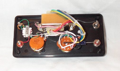
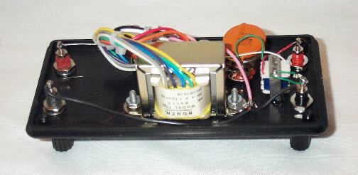
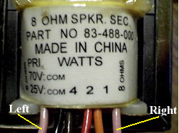
6) See photo below for proper phase ID of the two "pink" wires on the Bogen 725
transformer.
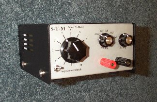
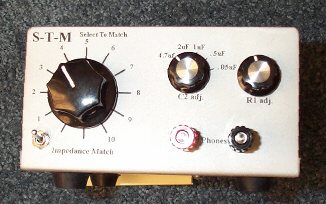
My version of Steve's S-T-M Calrad/Bogen
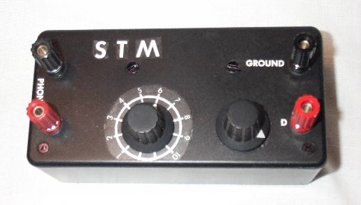
The S-T-M is excellent for comparison of headphones. It works very well for one or two sets of phones as well. It will run a range of headphones, from magnetic to sound powered.
More S-T-M circuits using different transformers are in the works to be placed here on this page in the near future.
Circuit Design by Steve Bringhurst "baldy3823"
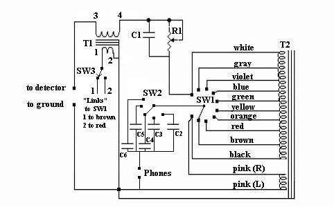
T1 Stanley audio transformer Part Number 227-E-1-3-98
Pri 100 ohm Sec. 100M (100k) ohm
(Fair Radio Sales number T3/AM-20)
T2 Bogen T724 4 watt P/A transformer (Grainger)
R1 250k ohm variable resistor
SW1 12 position single pole rotary switch (Radio Shack)
SW2 6 position single pole rotary switch (Radio Shack)
SW3 SPDT toggle switch (Radio Shack)
C1 .1 uf capacitor (Radio Shack)
C2 4.7 uf capicitor non polar (Radio Shack)
C3 2.2 uf capicitor non polar (Radio Shack)
C4 1.0 uf capicitor non polar (Radio Shack)
C5 .5 uf capicitor non polar (Radio Shack)
C6 .05 uf capicitor non polar - not shown in circuit can be
put in for 10k Hi "Z" headphones (Radio Shack)
Notes:
1) The range of C1 can be from .05uf to .22uf. It is not that critical.
2) Only ten of the twelve positions are used on SW1
4) #1 lead on T1 goes to SW3. It is split and one lead goes to brown on SW1 and the
other goes to red on SW1. This allows you to shifts the ratio range a full
step for better use of the Stromberg Carlson elements.
5) Experimentation is the key to getting the right values on this unit.
What is right for you and your set up is what counts.
6) See photo below for proper phase ID of the two "pink" wires on the Bogen 725
transformer.
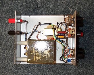
My version of Steve's S-T-M Stanley/Bogen
A Simple Dedicated Circuit
Now we will show a very simple circuits dedicated
to a particular set of headphones, but first,
you may want to go to Ben Tongue's web page
and read article #05 (maybe all of the articles).
Ben's Web site is at http://uweb.superlink.net/bhtongue/index.html.
This "fixed" setup is designed for standard 600 ohm impedance elements wired in series.
T1 Calrad 45-700 audio transformer (Ocean Electronic)
R1 Choice of R1 depends on radio set up, but 100k is a good choice
for diodes that measure around 96k ohms. See Ben Tongue's web
site for more information on this choice.
http://uweb.superlink.net/bhtongue/index.html.
C1 .1uf capacitor
C2 .47uf capacitorNotes:
1) The colors (green and white) on the transformer on the low
impedance side are interchangable. Polarity is not important
on this side of the transformer, but it is critical on the hi
impedance side (green and red).
If you have a circuit that you
use and would like to share it with others,
we would be happy to post it
here.
Please email me at "Removed"