Heliography
(Communicating with Mirrors)
by James Riddle - KD7AOI


|
Heliography (Communicating with Mirrors) by James Riddle - KD7AOI
|
In "Build Your Own Hg" you will find plans for several different heliographs. Keep in mind that you can get by with one Hg for learning and demonstration the instrument, but must have two heliographs for communication and real appreciation. The first by Dayton Ohio's Chris Brown is to me the easiest, and is a variation of the third (Waltner) plan. He utilizes strictly modern materials such as a dryer vent and camera release cable for the shutter. I find his use of the cable release is positively brilliant; it should help to cut down on disturbing the alignment of the heliograph while transmitting. To the illustrations will be added the designer's comments for each view when they are re-received (lost here in computer crash, together with Chris' address). The second is from an old German plan submitted by Henri Jacob F6GTC of France as shown in the first frame. Henri actually went on the build the German model, apparently within less than a couple weeks after he received the plans. Incidentally, the plans are written completely in German. The third plan is a quite a simple 4" heliograph employing aluminum foil reflectors. This design is by Willard and Elma Waltner, and published in the August, 1964 issue of Mechanics Illustrated. Don Loving, KM5OX, of Lone Grove, Oklahoma recently purchased the magazine and offered the article for publication on this website. It has the convenience of mounting on a camera tripod. I can't help but wonder if the Waltners didn't base their Hg on the German model? The fourth is a very complex wooden model patterned after the British Mark V. I can't imagine anyone in this day and age building this model, especially since Mark V's are sometimes available on e-Bay. However, I feverishly hope that someone does take the plunge and constructs the Hg. Notes: Believe it or not, it is possible to eliminate the sighting "holes" in the mirrors. Simply place an Avery dot in the center of the mirror and align the instrument as done with the Mark V Mance (for which sighting through the mirror is not possible). Instead, you look down into the sun mirror, making sure its dot, the sight (or duplex mirror dot) and target are all in the same alignment. Saves bending over, too, once you get the gist of it. I was reminded of using the dot by Edward Butler, KF6DXX of San Diego. I cut my teeth on the Kosel Model (see 'Homemade Hgs"), and became very frustrated with the my first Mance. Paul Smith, also familiar only with the Kosel Model as much as called me a liar when he first tried out a Mance. Tom has more recently been experimenting with using guitar tuners for adjusting the signal (also known as the sun or simplex) mirror. The tuners work fine except for the slack since there is no string tension. Perhaps someone would like to tackle this problem. You may find it useful to experiment with using aluminum foil for making, and/or covering your Hg mirrors. This material is introduced in the Waltner Plan. Doing may considerably cut down on the time necessary for adjusting (aligning) and operating the heliograph until familiarity is achieved. jhr
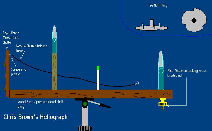
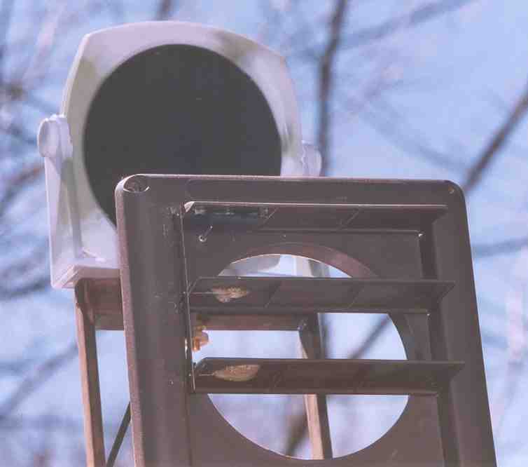
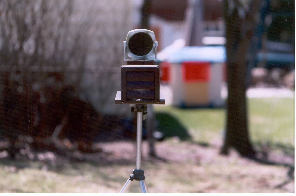
Chris Brown Heliograph, 2005
Photos that follow are numbered 1 through 10 from left to right.
Note: Instructions not yet "keyed" to photos. However, instructions below may be enough...jhr Chris Brown of Dayton, Ohio writes: "I recently 'found myself with a lot of free time' so I started researching heliographs, just for fun. I have attached a description of the Hg I built as well as a drawing. I will send photos as soon as I borrow a digital camera from someone!
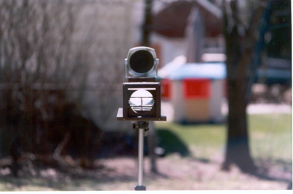
For my heliograph, I took the basic design from your website, �Build Your Own Hg� (�This design is by Willard and Elma Waltner, and published in the August, 1964 issue of Mechanics Illustrated at.�). I am not mechanically inclined at all so I made some modifications:
First,
I used 4-inch diameter vanity mirrors from the Dollar store.
These came in pivoting holders, with a magnifying mirror on one
side, so I didn�t have to make foil mirrors or holders.
I
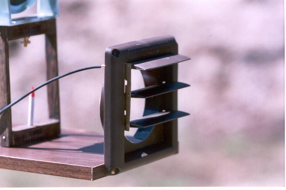
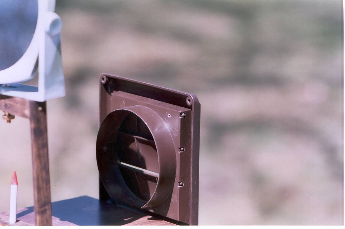
didn�t care for the round disc shutter suggested by the article so I
used a brown plastic dryer vent instead.
This has three slats and, just by coincidence, a 4 inch diameter
opening, normally used for holding the dryer vent hose.
I
was worried about the wood base warping so I used a �fake wood�
shelf piece as my base. It
is 24�x 7 7/8�x 3/4�
and has a dark veneer.
I found some nice brass knurled nuts that looked like something
that would be used on a 19th century telegraph so I used them, with
brass bolts (with angled, flat heads), to hold the mirrors instead of
boring ol� wing nuts. The mirror bases already had holes for mounting
so I just drilled out some mild countersinks so the
angled, flat bolt heads would not interfere with the mirrors
pivoting.
I had to break open the case on one set of mirrors in order to scrape a sight hole in the silvering. The mirrors in each set are held in a plastic disc inside the case. I removed the magnifying mirror and replaced it with a very thick piece of cardboard, cut to size and with a much larger than needed hole in the center (about 1 1/2 inch in diameter - I didn�t want to risk misaligning things).
In order to make the sighting hole, I first drew several arcs on
the back of the mirror, using a compass, in order to locate the center.
I then took a piece of reflective tape, from the auto parts
store, and used a hand-held paper punch to put a 1/8 inch hole in it
(probably too big). I only
used reflective tape because A) that�s what I had and B) it is thick
so the tape wouldn�t deform as I scraped off the silvering.
For the scraping I used a Swiss Army knife and a 1/32 inch
precision screwdriver. Then
I re-installed the mirror, cardboard and plastic disc and cemented the
case back together. The
mirrors tended to spin too freely in their frames so I cut discs out of
old t-shirt and put one in each pivot hole, in order to add a bit of
friction. That worked
great!
The frame was the most difficult -
I used � inch square wood stock and a � inch molding that had
rounded corners on one side. After
gluing it up and clamping it, it came out not quite flat and square;
but it should do. I
painted my � inch sighting
wood dowels white, with the top of the notched one �hi-viz� green
and the pointed one hunter orange.
The holes for those aren�t perfect, either but they line up.
I decided to drill holes for two other wood dowels - they�re
glued in the frame but stick out a bit at the bottom to fit into holes
in the base and allow the frame to be removed, rather than permanently
attached. I figured that
would make transporting easier/safer.
The dryer vent/shutter was a bit of a challenge:
I used a piece of thin brass sheet and straight pins to connect
the slats. The slats are
curved so I was able to push the pins into the support edges (I had to
heat the pins with a lighter to get them to go through the plastic).
At first I ran into trouble because the middle and bottom slats
would not close completely. It
turned out the brass piece was hitting the plastic pivots on those
slats. After filing small
grooves in the brass the slats closed much better (though still not
completely. Probably
another misalignment problem with the straight pins in the slats.
But they close enough to not be a problem).
When I got everything working okay, I used small globs of Gorilla
Glue on the underside of each slat to hold its straight pin in place.
Gorilla Glue foams up and expands so this ensured the straight
pins would be fully encased.
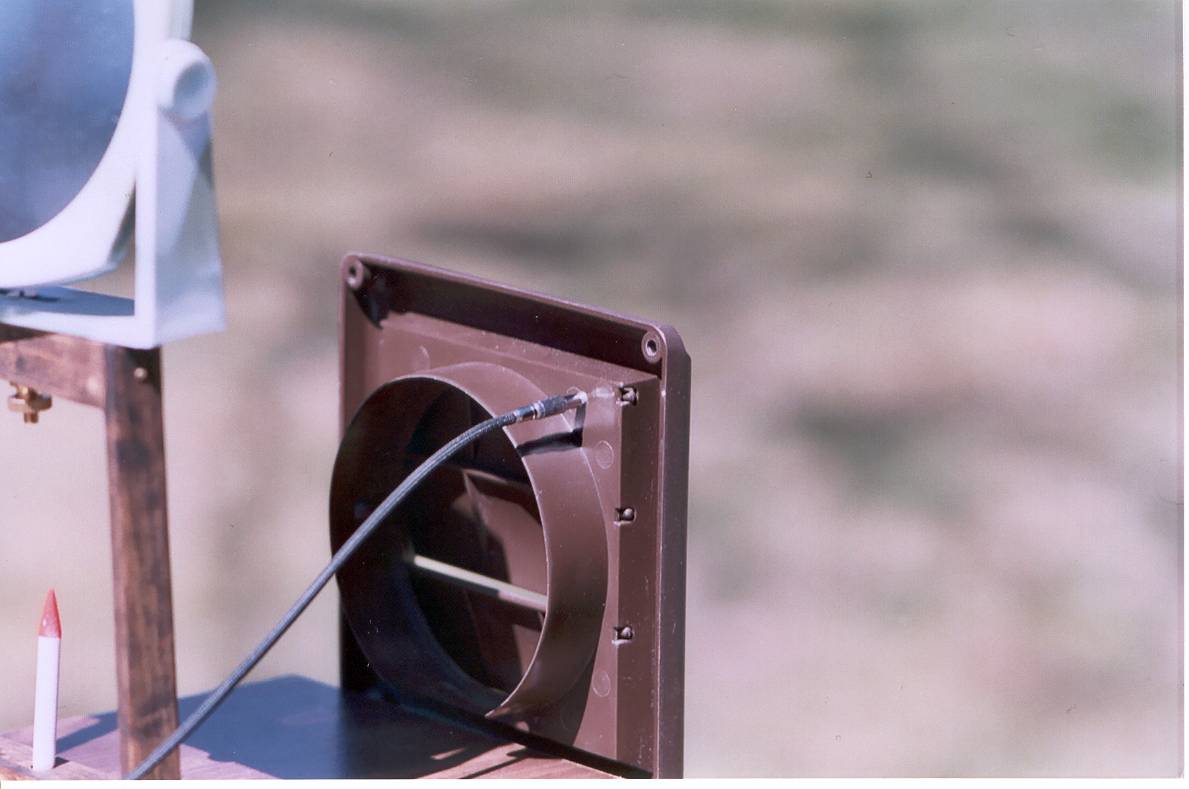
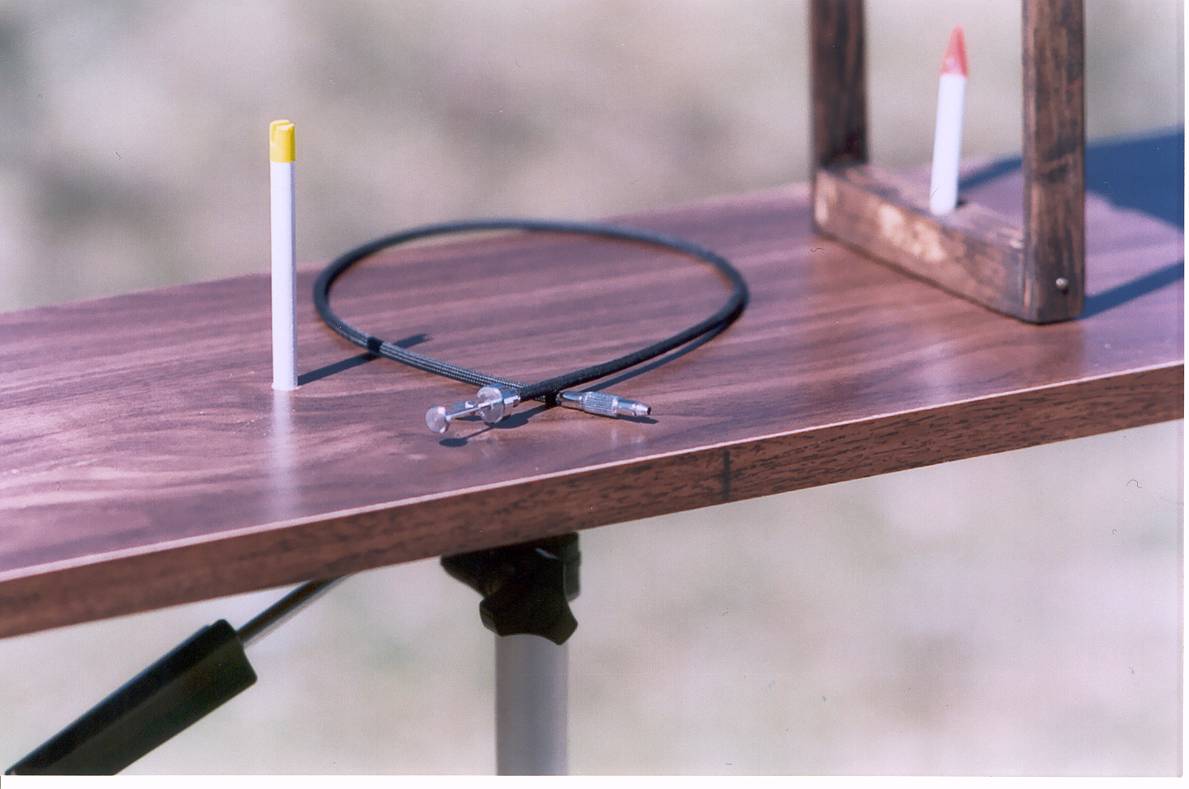
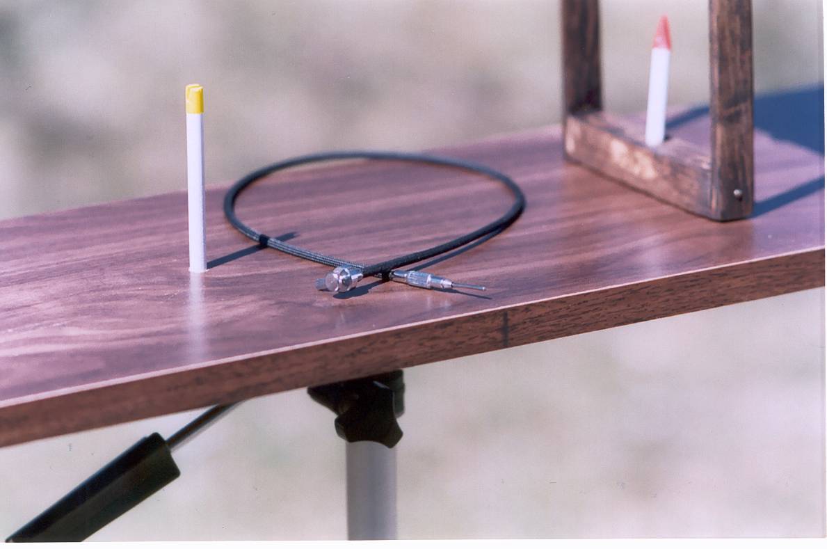
To operate the shutter, I decided to use a camera shutter release
cable, rather than something complicated, again because I have one.
The screw head on the cable is tapered so all I had to do was
drill a small pilot hole into the �shutter,� just below the top edge
of the top shutter and work the cable�s screw in and out a few times
in order to �tap� the plastic.
However, because the dryer vent�s slats are curved, the release
cable was not able to open the shutter a full 90 degrees.
For that I shaped a flat piece of plastic, actually the battery
cover from an old VCR remote control.
The plastic piece had two tabs on one end and a small ridge on
the other - perfect for gluing! I
roughed up both surfaces a bit with sandpaper, placed the plastic piece
and clamped it with two spring clothes pins.
The plastic piece also covers the straight pins / glue glob on
the top slat - the other two slats look pretty ugly from the back, with
these bubbly globs of Gorilla Glue on them!
Rather than drill a hole in the �geographical� center of the
bottom of the base, I attached all the pieces of the Hg and placed it on
a pencil, rolling it back and forth, length-wise, until I located the
�balance� center. I
then drilled a hole and hammered in a �Tee Nut Fitting,� which had
the same threading as my camera tripod (yes, I had to take my tripod
with me to the hardware store). Tee
Nut Fittings also comes in a type that has holes for three nails, brads
or screws, but that type did not have the correct size threading.
After hammering it in place and mounting the Hg on my tripod,
there was a bit of space between the bottom of the Hg and the tripod
base - I had to remove the Tee Nut Fitting and chisel out an small area
so the Tee Nut Fitting would sit flush.
This was not pretty but it works, thought the Hg still can wobble
a bit front to back (I blame this on the rather short tripod mounting
screw, rather than my carpentry skills).
And, since the tines on the Tee Nut Fitting bend/bite into the
wood when you hammer it in place, my original could not be used again so
I had to go buy another (a whopping 33 cents!). Since I�d found that brass knurled nut and had the pieced of brass sheet, I decided to use brass for all the hardware. The only things I couldn�t find were brass (or at least yellow metal plated) straight pins and the Tee Nut Fitting.
Chris Brown"
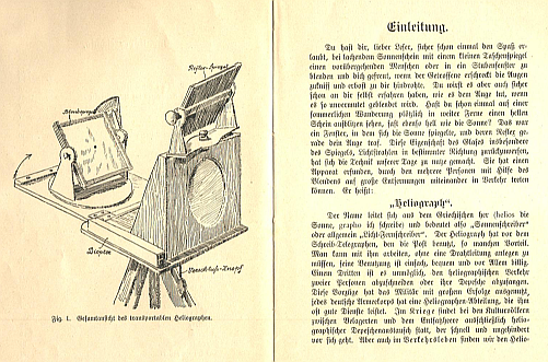
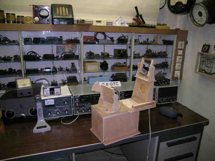
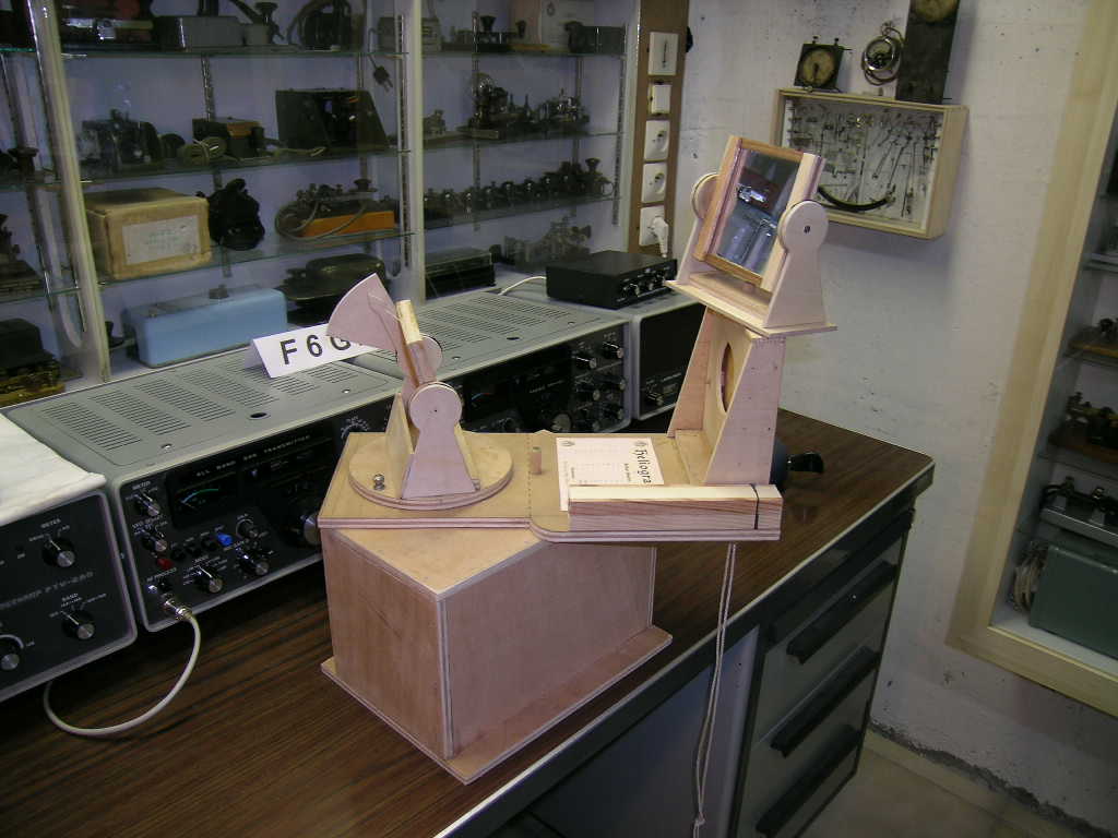
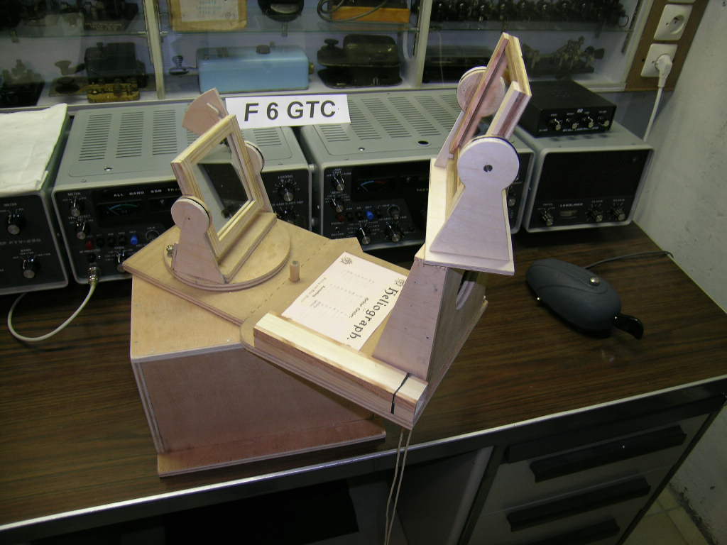
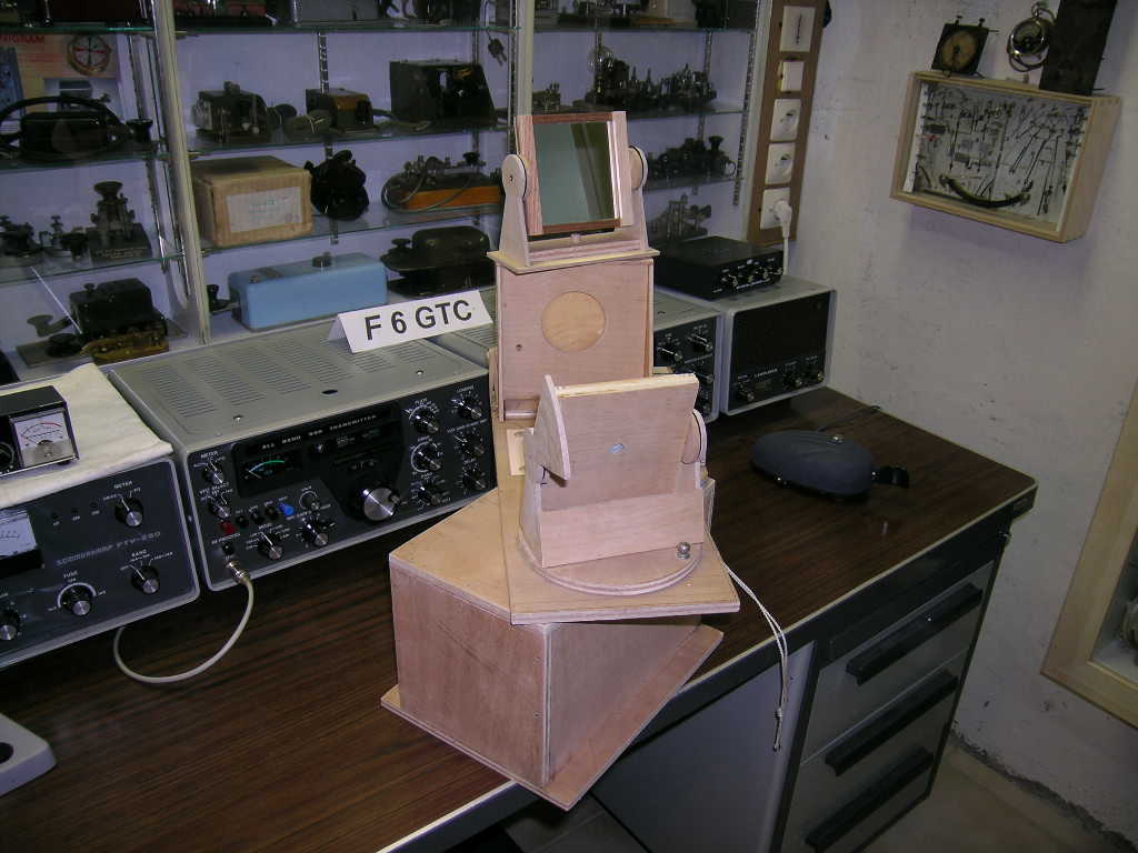
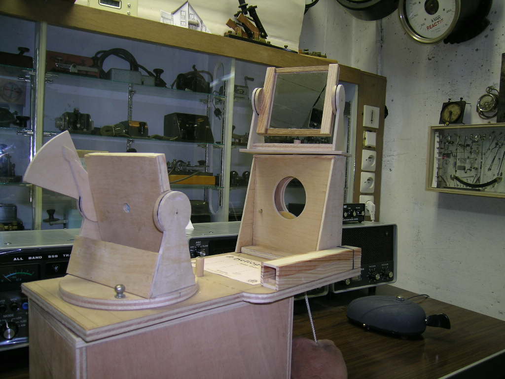
Henri Jacob's "German Model" Helio, May, 2005
On April 14, 2005 Henri wrote, "I just received the book with the german helio, so I can't wait longer, and send you a picture of the item mounted. Unfortunately, one sheet with drawings is missing. But I found a carbon sheet used to duplicate it! I think it will be a hard job to make the piece, please don't be in a hurry! I'll do my best and give you news as soon I understand how all the pieces work together! And don't forget, the book is titled "Spiel und Arbeit" as game and work; there is no date on it. Just some first indications: Blendspiegel, or Blending mirror (with the "hole" in the middle called the "Festpunkt" as fixed point meaning it doesn't move in any position of the mirror), Reflexspiegel, or reflecting mirror, Verschlussknopf or shutter key, and Diopter or view finder. The arrow on the left indicates that the system can be tilt up for the transport." On May 2nd, "I'm trying to make and assembly the German helio, will surely take a lot of time. But I'm on the right way to do it, one drawing missing and XYL (ham jargon for "ex young lady", or "wife") who doesn't understand why I'm so long away in my shack! The principal is quite the same that for the helio from the article "flashing with the sun ", just a little bit heavier like most of german items". And on May 5th "I just roughly finished building the German helio, no painting, some finishing to do, but it's operational. So I cannot wait longer and am sending you some first pictures of it. The translation of the manual will start soon. Just don't forget it's only a toy and has nothing to compare with a real Mark V helio. As you can see it looks very similar to the one of the �flashing with the sun� article."
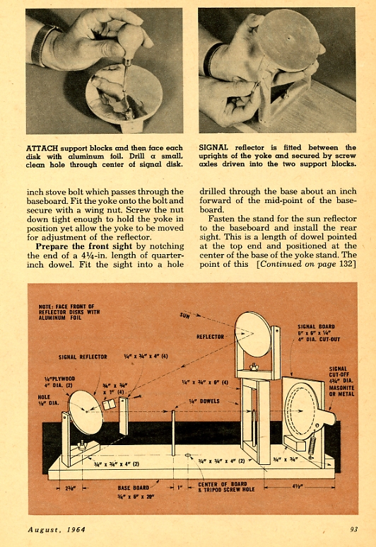
Willard and Elma Waltner's Heliograph, 1964
Notes: I doubt the upper mirror can pick up the sun from "any direction"; it's use is limited to sun being behind operator. Also, I suggest removing upper mirror and using only the lower mirror for signalling when sun is forward of operator. Good idea using foil for the mirror surfaces as adjustments wouldn't be nearly so critical since sunlight will be reflected in many directions (with "Prehistoric Heliographs", I discovered mica was much better than a mirror for light dispersion (piece of cake at distances tested). Another possibility would be to use reflective tape. I mounted a tape reflector across the road from Prescott's Sharlot Hall Museum, and it works fine but with less reflective bandwidth as would foil. And isn't there a foil with a diamond pattern? Finally, the shutter isn't as fast as others, but should be perfectly suitable for 3 to 5 words/minute code, especially if shutter is quickly flicked. jhr
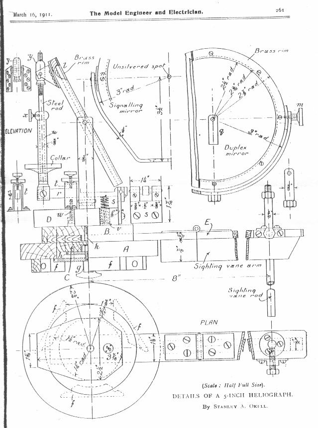
OKELL HELIOGRAPH, 19ll The fourth is a much more complex 5-in. Heliograph (similar to the British and Canadian Mark V's. The plans are contributed by John Goldfinch of Stevenage UK for his contribution of the following images and narrative. Stevenage, by the way, is 30 miles north of London, but is it a museum or a town? The plans are from John's March 16, 1911 issue of "The Model Engineer and Electrician.", pages 259 - 262, by Stanley A Okell, A.C.G.I.
|